
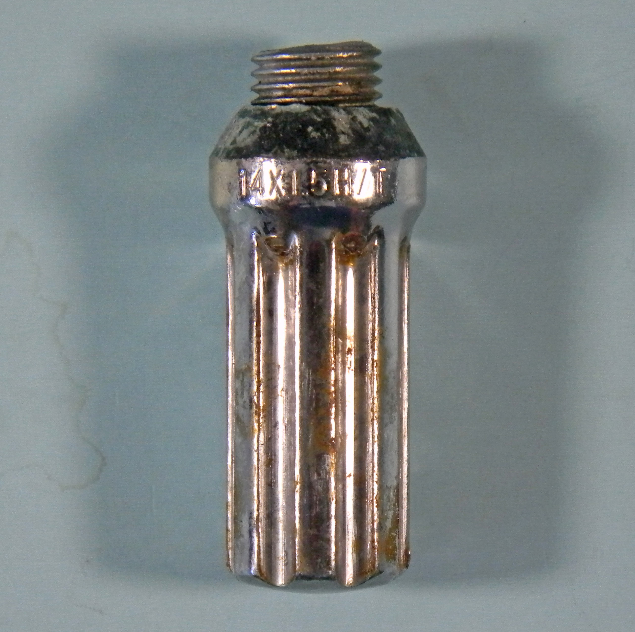
On July 6, 2023 I drove west on U.S. 20 past Burns Oregon, which I blogged about on July 29, 2023 in a post titled A trip to Lake County, Oregon’s Outback. My right leg had a cramp, so I pulled off, parked on the gravel, and walked around. I found the broken 14 mm diameter wheel bolt shown above. Based on its fracture surface appearance I could immediately tell it had failed progressively by fatigue. There are parallel macroscopic stripes called beach marks, and steps called ratchet lines (arrow). Wikipedia has an article on Fractography which says that:
“Fractography is the study of fracture surfaces of materials. Fractographic methods are routinely used to determine the cause of failure of engineering structure, especially in product failure and the practice of forensic engineering or failure analysis.”
I described it generally in an article (co-authored by R. S. Carbonara) titled Don’t Let Your Case Rust Away and subtitled Evidence preservation vital of surfaces produced by fracture which was published in the April 1994 issue of Claims magazine starting on page 71. We said:
“Fractography can be used to determine in which direction(s) the crack(s) grew, and thus to identify where cracking started (the origin or origins). Examination can also determine whether fabrication defects are present at the origin (s). Fractography can also determine whether cracking occurred continuously or intermittently. Finally, a detailed microscopic examination can reveal by what path and mechanism fracture occurred...
Examination of fracture surfaces may involve several steps with a range of magnifications from the naked eye up to 50,000 times.
The first step of the examination is to document the ‘as received’ fracture appearance by close-up photography and macrophotography. The second step is to examine the surfaces using a stereo optical microscope at magnifications of up to 100 times.
These steps will usually reveal the crack origin and crack growth directions, and whether cracking occurred continuously or intermittently. Careful cleaning of the surfaces also may be required at some point in the examination process.
Determination of the microscopic path and mechanism of crack growth usually requires a third step, which is to examine the surfaces with a scanning electron microscope (SEM). This is at times considered a destructive test, since it may require cutting the part to produce pieces that will fit into the SEM. If cutting is permitted, then at that time samples should also be taken for other destructive tests which usually include composition, microstructure, and hardness. These tests can both improve interpretation of the SEM results and lead to determination of whether the material or its processing contributed to the failure…
Repeated cycles of loading can cause cracks to initiate and grow, a process called fatigue. The fatigue cracks will grow until the remaining cross-section can no longer carry the load, and fracture occurs.
In fatigue, the deformation only occurs locally and repeatedly at the tip of the growing crack. This repeated opening and closing of the crack tip forms microscopic features called striations. Striations are rows of parallel hills and valleys which appear similar to the surface of corduroy fabric or a plowed field.”
There is an excellent article at the Fastenal web site titled Fastener Fatigue. It has sections titled:
What is fatigue?
What does a fatigue failure look like?
Why do fasteners fail in fatigue?
What ways are there to combat fatigue?
Another more general article by Shane Turcott titled Bolt Failures – Why learn to recognize mechanical failure modes appeared in June 2021 at the web site ot the Society for Maintenance & Reliability Professionals (SMRP).
On September 19, 2015 I blogged about Do you see things differently than your audience? Explain how to them. In that post I described fracture features called chevron markings that result from brittle overload fracture (as shown above).
No comments:
Post a Comment